

Technical Introduction and Scope Framing
Two things decide whether a Honda VFR400R NC30 build comes together or fights you for a month: the side vent openings and the exhaust clearance. Panel alignment, decal placement and paint depth can all be recovered later. Those two cannot.
The vents are structure, not styling. A 90-degree V4 in a 1,345 mm wheelbase leaves the rear cylinder head, the gear-driven cam train and both header runs packed inside the fairing, and the mid-panel openings are where most of that heat gets out. An opening that comes out undersized, or a few millimetres off the OEM datum, raises the temperature under the cowl and pushes the panel around it toward distortion.
The exhaust sets the lower cowl envelope. The NC30’s 4-into-2-into-1 collector passes close to the belly pan, and the gap Honda specified there has to absorb suspension travel, engine movement under load and thermal growth in the pipe. A lower fairing that loses that gap will touch the collector under hard braking, then heat-cycle into warped laminate or softened ABS.
So whether a set of Honda VFR NC30 fairings fits cleanly, flows cooling air where it should and survives engine heat comes down to how faithfully those two interfaces were reproduced, by Honda’s tooling or by a replica mould.
What follows covers the vent anatomy and what the airflow actually does, the exhaust routing and how to measure clearance, fitment tolerances at the mounting points, trimming procedure for replica panels, thermal management under sustained load, and where to source Honda fairings that hold these dimensions. It is written for people who intend to ride the result, not detail it for a show.
Side Vent Anatomy and Airflow Function
On an NC30 the side panels do cooling work. Each vent sits just aft of the fairing stay pickup and opens into the low-pressure region beside the frame spar, so the opening is the exit for air that has already crossed the radiator and the rear bank. That pressure drop across the bodywork is what keeps the air moving. Get the geometry wrong and the symptom shows up as oil temperature and heat soak around the headers rather than on a dyno sheet.
- Rear-bank cooling. Air that enters at the nose has to leave somewhere, and the mid-panel vents are the main way out. Because they sit behind the rear cylinder head, the air crosses the cam cover and the exhaust stubs on its way through, which is useful in the hottest, most enclosed corner of a V4 crammed into a 400-class package.
- Pressure relief inside the bodywork envelope. Seal a fairing and it behaves like a balloon. Air piles up at the nose with nowhere to go, positive pressure loads the panels, the fastener seams start to flutter and the flow you wanted stalls. The louvred outlet in each side panel gives that trapped volume a route out, which drops the pressure differential across the bodywork and lets heat leave instead of recirculating.
- Louvre geometry and angle set the flow rate. Pitch, open area, edge radius and blade angle against the local surface all change the discharge coefficient. Shallow blades vent quietly and move little air; too steep and the louvres trip the boundary layer and dump turbulence onto the rear wheel. Original panels sit in the 20-30 degree range, and the break line around the vent is moulded rather than cut, so the louvres keep their stiffening lip.
| Vent detail | OEM ABS panel | Typical replica GRP panel |
|---|---|---|
| Louvre angle | 20-30 degrees | 15-20 degrees |
| Total vent opening area (per side) | approx. 70-80 cm2 | approx. 55-65 cm2 |
| Panel material thickness | 2.5-3.0 mm | 1.8-2.5 mm |
| Louvre edge finish | Molded radius with stiffening lip | Hand-trimmed, often square-edged |
| Mounting method | Mounting tabs plus Dzus fasteners | Often tabs only, holes pre-drilled oversize |
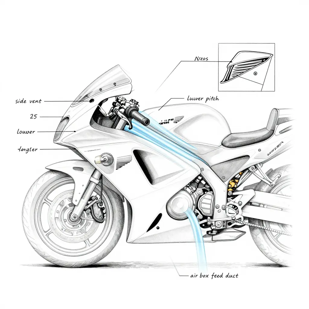
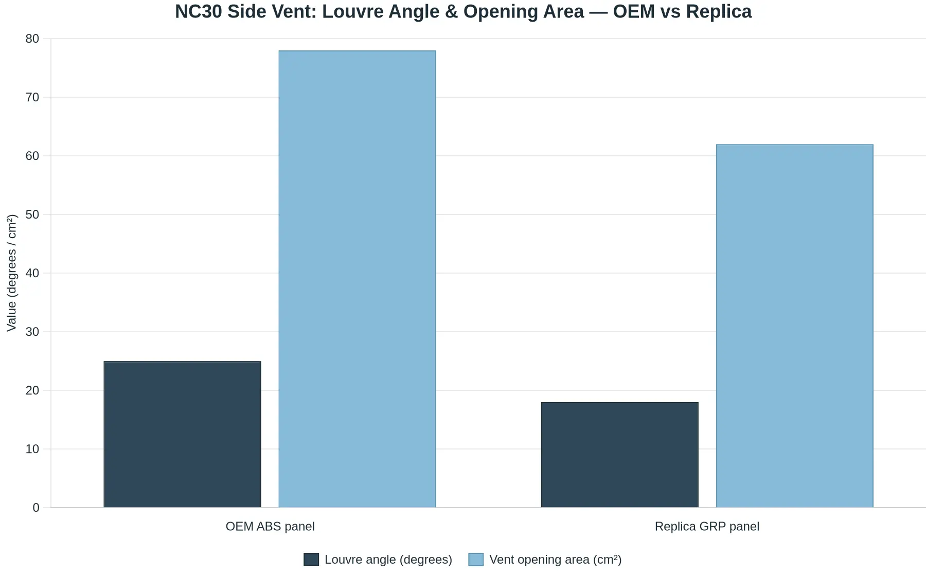
The vent also has a visual job. The break lines running off the louvre block continue straight into the shoulder crease of the RC30-style bodywork, so the panel reads as one form from nose to tail, which is a large part of why some builds look convincing and others look assembled. Replicas give themselves away here first: vent openings get reshaped for mould release, the break line softens, the tabs thin out and the louvre angle drops back. Before paint, sight the vent break line against the tank seam, test-fit the fairing stay bracket and check that every fastener goes in without preload. If a panel needs force to sit flush, its vent geometry is fighting the airflow path it was meant to feed. If you want panels moulded from the original vent profile, the custom Honda fairings range is where to look.
NC30 Side Vent Opening Layout: The 2D Reference Diagram
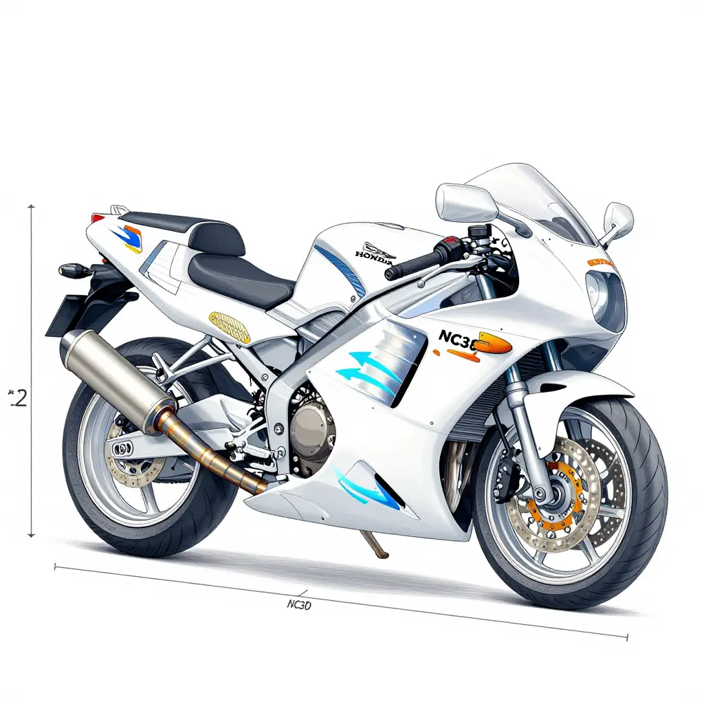
Before you drill, trim or pay for replica panels, it helps to see the vent geometry as lines instead of glossy photographs. The schematic below reduces the NC30 upper and lower side panels to what matters: aperture boundaries, louvre direction and the small tabs that carry the panels.
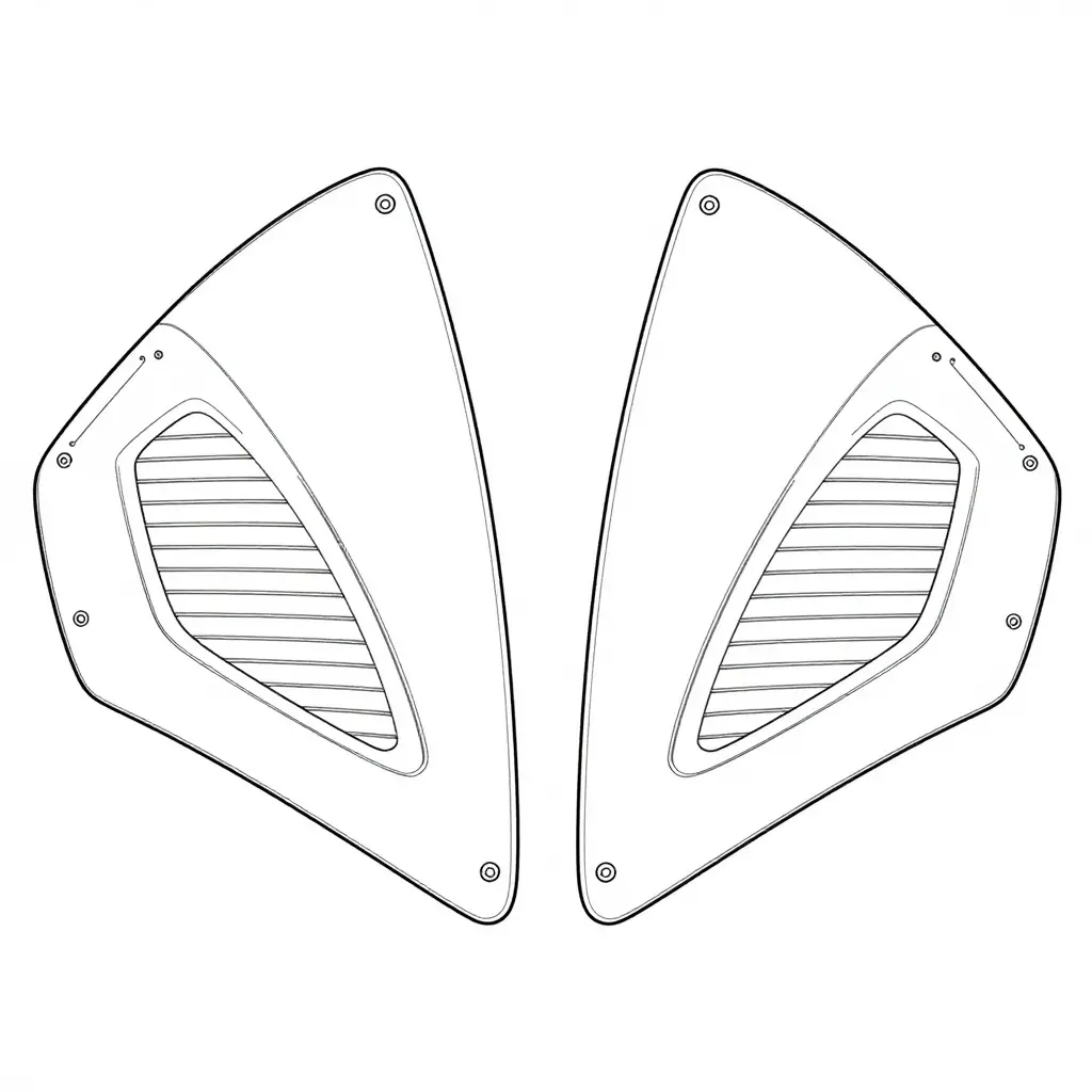
How to read the drawing
- Vent boundary shapes. The openings are angular, roughly triangular, and widen toward the rear of the panel. That taper follows the airflow out of the radiator shroud and past the front cylinder head; it is not a styling flourish.
- Louver orientation. Each slat appears as a single parallel line set at an angle to the flow. Slat pitch matters more than most builders assume, and replica louvres laid at the wrong rake will stall the vent and trap hot air around the header.
- Mounting tabs. The small rectangles at the panel edge mark tab positions and bolt holes. Count them on your own parts before trimming anything. A mismatch here usually means the panel was never an NC30 moulding.
- Left/right symmetry. The two panels are drawn mirrored. Run a straight edge along the drawing, then compare it with the physical panels: asymmetry on one side is crash damage or a mould that was pulled badly.
Quick reference for verifying your own panels
| Feature | What to confirm on the part | Typical failure point on replicas |
|---|---|---|
| Vent aperture | Angular taper toward the rear edge | Opening too small or squared off |
| Louver slats | Even pitch, consistent rake angle | Slats cast in flat or missing entirely |
| Upper panel tabs | Matches diagram count and spacing | Tabs too thin, crack at the root |
| Lower panel tabs | Aligns with upper panel mount points | Holes offset by several millimetres |
| Left/right pair | True mirror image | One side moulded from the other |
Print the schematic and lay it beside the bike during a dry fit. If the vent outline traces cleanly onto the panel and the tabs line up with the frame and bracket holes, the set came from a genuine NC30 shape rather than a generic sportbike mould.
If you are comparing moulds before buying, a range of custom Honda fairings gives you a visual baseline for how vent openings and tab positions are presented on correctly shaped bodywork.
Exhaust Clearance Fundamentals
On the NC30 the exhaust does more than fit under the bodywork: it defines the envelope the lower fairing has to respect. The front-bank headers leave their flanges close to the radiator core, drop behind the front wheel and turn rearward. The rear bank exits under the seat unit and curves down past the shock. Both streams meet at the collector junction under the crankcase, the most congested point in the layout, and from there the system runs back to the single silencer on the left-hand side of the bike. That pipe sits close to where the lower fairing’s compound curves want to be, and the left-hand lower panel carries the moulded relief that keeps the two apart.
Honda dealt with this by moulding a relief into the inner skin of that panel, a local scallop that buys back 15-20 mm without disturbing the outer profile or the side vent openings. Replicas frequently flatten that relief, shift it rearward or leave it out entirely, and that is where clearance problems start on any full bodywork build. Compare the inner skin of a candidate panel against an OEM part before ordering: the relief should be a clean, deliberate depression, not a stretched bulge someone warmed with a heat gun. Honda VFR NC30 fairings in a catalogue photo will show the shape, but confirm it against a physical reference panel before paint.
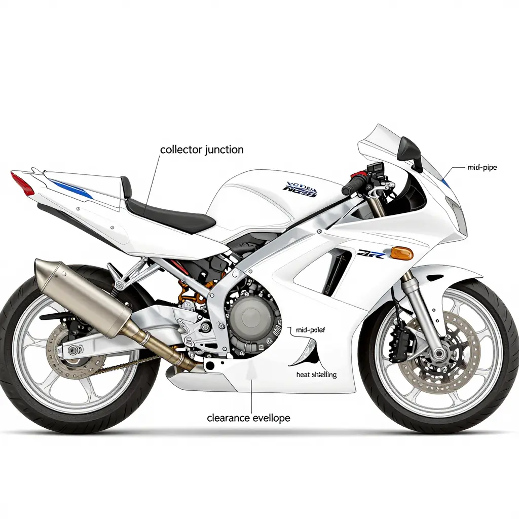
Static Clearance Is a Cold, Unloaded Number
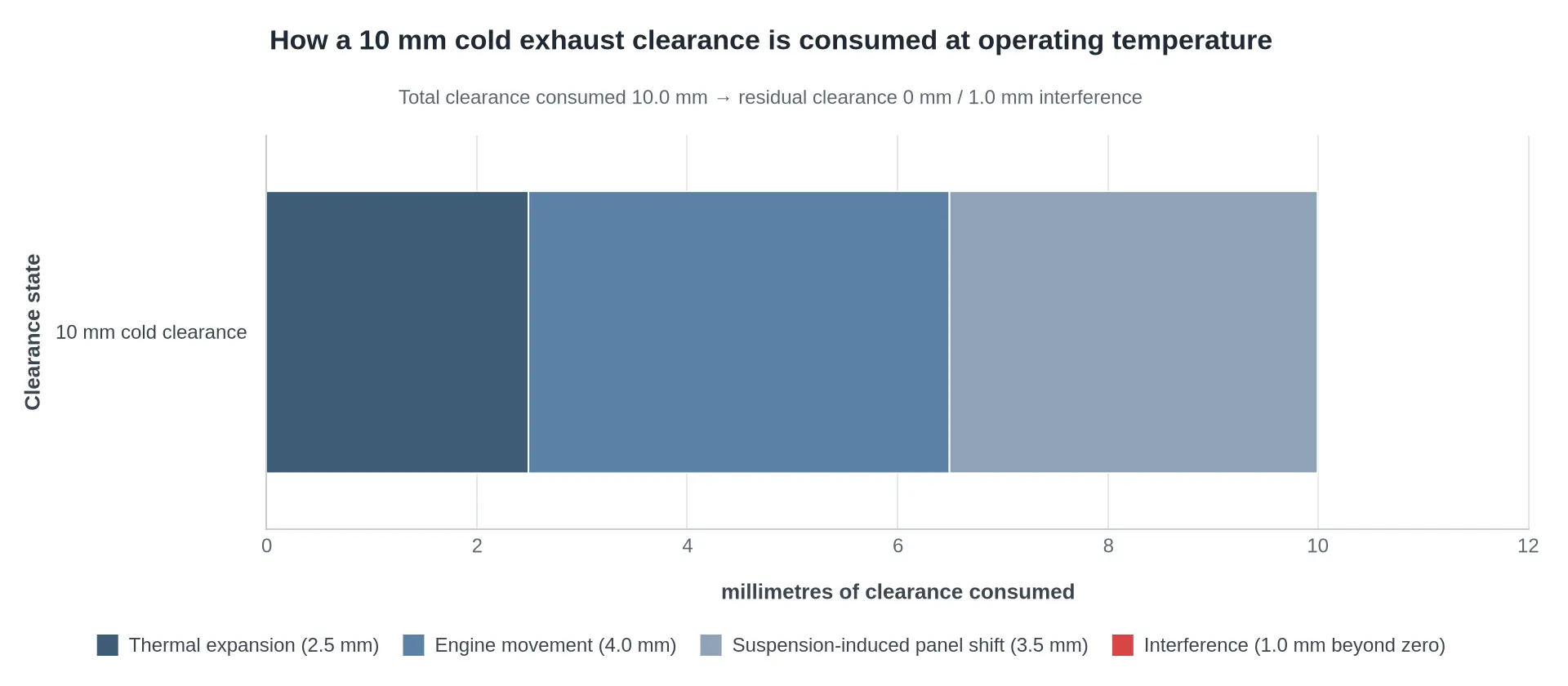
A feeler gauge reading taken cold on an unladen bike is optimistic by definition. Three things eat into it: thermal expansion of the stainless system (roughly 1.7 x 10^-5 per degree C, about 2-3 mm over a 400 mm run at operating temperature), engine movement on its mounts under torque reaction and over bumps (3-5 mm at the collector), and suspension travel, which swings the lower fairing relative to a fixed pipe as the forks compress. Shielding costs clearance too: a 2 mm alloy shield needs its own 3-5 mm air gap before it does any good.
| Interface | Minimum static clearance | Reason |
|---|---|---|
| Header pipe to inner lower skin | 10 mm | Radiated heat, fork travel |
| Collector junction to belly pan | 15 mm | Highest surface temperature, engine movement |
| Mid-pipe to relief cut | 12 mm | Long unsupported run, vibration |
| Heat shield to pipe (air gap) | 5 mm | Convection gap – shield must not touch |
The Practical Minimum: 10 mm, No Exceptions
Ten millimetres is the floor at any pipe-to-panel interface, 12 mm at the header and 15 mm at the collector, where the surface runs hottest. Check it twice: once with the suspension fully extended, once at full compression with the bike loaded. Only the smaller figure counts.
Why ‘Close Enough’ Fails
Five millimetres feels generous in the workshop. Add 2.5 mm of thermal growth, 4 mm of engine movement and a panel shift from suspension travel, and you are through zero at 8,000 rpm on a hot day. Contact does more than scuff paint. It feeds vibration into the laminate, star-cracks the gelcoat around the mounting tabs and blisters the inner skin wherever a shield is pinned against the pipe. Worse, once a panel has been pushed outward, every other joint inherits the error: the upper-to-lower seam, the belly pan, the fastener stack behind the vent. Measure the exhaust first, set the envelope, then build the rest of the bodywork around it.
OEM vs. Replica Honda VFR NC30 Fairings: Hard Reference Data
The table below puts the clearance and tolerance numbers side by side, so a buyer can weigh aftermarket NC30 bodywork against known OEM benchmarks before committing to a set of Honda fairings.
| Specification | OEM Honda panels | Premium ABS replica | Budget replica |
|---|---|---|---|
| Side vent opening dimensions | 148 x 63 mm nominal, 3 mm edge radius, molded inner duct lip | 147 to 149 x 62 to 64 mm, 2.5 to 3 mm radius, duct lip molded in | 140 to 146 x 58 to 63 mm, 1 to 2 mm radius, lip often flat or missing |
| Panel wall thickness | 2.8 to 3.2 mm, high-pressure molded | 2.6 to 3.0 mm, consistent across panel | 1.8 to 2.4 mm, varies plus or minus 0.5 mm |
| Exhaust relief cut accuracy | CNC trimmed, plus or minus 0.5 mm, follows header arc | Plus or minus 1.0 to 1.5 mm, hand finished | Plus or minus 3 to 5 mm, hand cut, filing expected |
| Mounting hole alignment | Molded pilots within 0.3 mm | 0.5 to 1.0 mm, pre-drilled, occasional slotting | 2 to 4 mm off, plan to ream or slot two to three holes |
| Heat deflection under sustained exhaust load | No measurable sag with OEM shielding in place | No sag to 150 C, slight gloss change above 130 C | Visible sag or warp at 110 to 120 C, shielding mandatory |
| Finish preparation before paint | Scuff and primer only | Sand 400 to 600 grit, fill flash lines, primer | Heavy filler work, pinhole mapping, 800 grit, multiple primer coats |
Reading the table: builds fail on the vent opening and relief cut rows, because that is where a few millimetres lost at the duct edge turn directly into clearance lost against the rear header. Budget panels can be made to work, but the money saved at purchase usually goes back out in filler, filing and heat shield fabrication.
Test-Fit Checklist: Sequenced Steps for a Complete Honda VFR NC30 Fairing Set
Before a drop of primer goes on, every part needs to be proven on the bike. The order below is the procedure the rest of the build hangs off, the point where understanding how the bodywork is designed turns into tolerances that hold at speed. Work through it in sequence, bike on a stand, suspension unloaded where noted, notebook or phone camera within reach.
Mount the upper fairing to the stay first, with every other panel off. Slide it onto the front stay and run all four mounting points down finger-tight. The panel should sit with even gaps at both headlight cutouts and no more than 2-3 mm of lateral play at the mirror mounts when you push it side to side.
Check the vent openings against the frame spars before you tighten anything. Sight through each vent and confirm the opening clears the frame’s main spar and the radiator duct mouth by at least 5 mm, so the panel cannot flex into the frame under braking.
Dry-fit the side panels to the upper and the lower rails using the fasteners only. Each panel should pick up its upper locating tab without force, and every fastener should seat on the first or second push. If you have to lever the panel into place, the tab angle is wrong.
Trial-fit the lower and belly panels onto the completed upper assembly. Bolt the lowers to the side panels and check that the belly pan seam runs parallel to the frame cradle on both sides. Seam heights that differ by more than 3 mm mean a twisted lower or a bent subframe.
Verify exhaust clearance at the collector with the panels fully assembled. Bike cold, on a paddock stand, slide a 10 mm spacer or a folded shop rag between belly pan and collector. It should pass freely along the full length of the collector without the panel deflecting.
Repeat the clearance check with the rear suspension compressed. Strap the rear down or load the bike until the shock is roughly 60-70 mm into its travel, then measure again at the mid-pipe and the collector joint. You still want 8-10 mm there, because the swingarm and the pipe move relative to the bodywork.
Confirm that both vent openings sit symmetrically left to right. Measure from a fixed datum (the frame headstock centreline or the swingarm pivot) to the front and rear edge of each vent. More than 5 mm of difference means a bent stay or panels laid up asymmetrically.
Mark every relief area in pencil, not with a grinder. Circle any contact point at the collector, mid-pipe, radiator duct, frame spar and wiring loom, then photograph the marks against a tape measure so you can compare before and after trimming.
Check fastener alignment through the full stack. With all panels loosely fitted, every bolt hole and quarter-turn fastener should land within 1 mm of its clip or bung. Do not elongate holes yet: torque the assembly to spec first and re-check, because flex often closes a gap that looked open.
Prove you can still service the bike. With the bodywork fully installed, check that the oil filter spins off by hand and that a plug socket with extension reaches all four plug holes without touching a panel. If routine servicing means loosening bodywork, mark that panel for a relief cut now.
Finish with a walk-around and a disassembly rehearsal. Strip the set in the reverse order of fitting, count the fasteners, and note every panel that needed force. Those are the spots to revisit before paint, so the finished Honda VFR NC30 fairings go back on with fingers only.
Why Sequence Matters More Than Speed
Replica bodywork rarely fails at the paint stage. It fails because a panel was forced into place during a rushed trial fit and then cracked six months later at a stress riser. If the set arrives out of tolerance or you are still sourcing panels, a Honda fairings collection built specifically around these classic sportbike platforms saves you from chasing someone else’s moulding errors. Once the checklist passes cleanly you have the baseline you need to set final tolerances, and only then should the panels come off for prep and colour.
Fitment Tolerance and Measurement: Building a Baseline Before You Cut
Ruined replica panels usually start the same way: someone eyeballs a gap, decides it “looks tight,” and reaches for the sanding drum. The cure is not patience, it is a method. Before trimming Honda VFR NC30 fairings you want three numbers in a notebook and one rule worth keeping: never remove material to fix a gap you have not measured twice.
Take the OEM-versus-replica figures from the table above, measure the same checkpoints on your own bike, and walk into the trimming stage with a target instead of a hunch.
The tools that actually earn their bench space
No metrology lab required. Four items and a notebook.
- Feeler gauges (0.05-1.00 mm set). The only honest way to quantify exhaust clearance at the header. A 0.40 mm blade that slides freely and a 0.50 mm blade that will not puts the gap at roughly 0.45 mm, which is a number, not “close.”
- Flexible steel or cloth tape (1 m). Rigid rules bridge across curved fairing surfaces and lie to you. A flexible tape follows the contour, which is what left-to-right vent comparisons need.
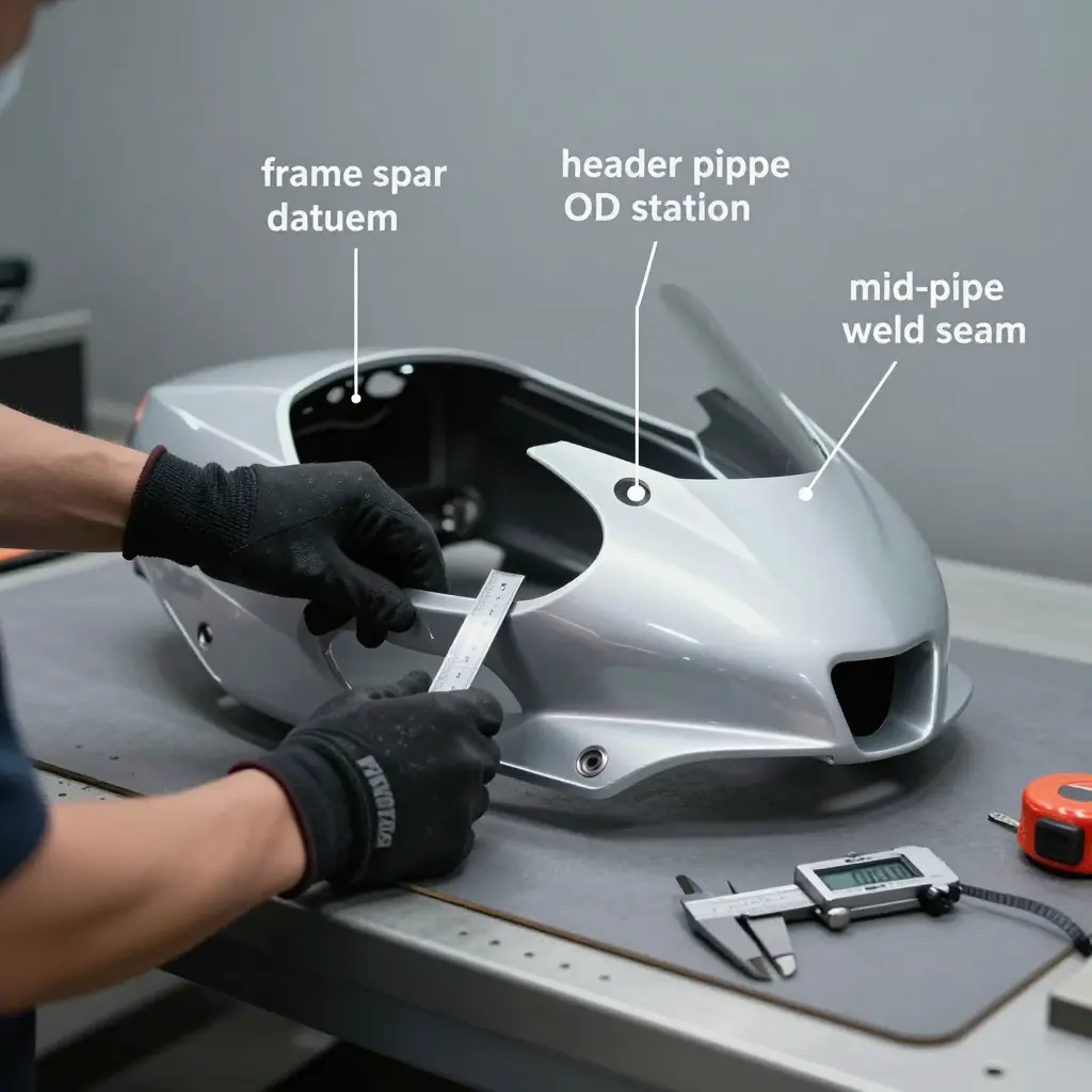
- Digital calipers (150 mm, 0.01 mm resolution). For header pipe OD at a fixed station, the width of the mid-pipe weld seam, and panel thickness at the vent lip before and after trimming.
- Log sheet, painter’s tape, fine silver marker, torque wrench. Tape dots keep you measuring the same spot on both sides. The torque wrench earns its place too: an uneven tightening sequence clamps a panel out of position and reads as a defect that is not there.
Fix the datum set first, then never move it
Repeatable numbers need reference points that do not belong to the panel you are judging. On an NC30, four will do:
- Frame spar – the outer face of the left and right upper spar, measured 40 mm aft of the headstock gusset. This is the master datum for fore-aft and lateral position.
- Header pipe OD station – a fixed point on the front header, say 50 mm below the port flange, always measured perpendicular to the pipe centreline. Never assume a nominal diameter; aftermarket headers vary by a millimetre or more.
- Mid-pipe weld seam – a stable feature that does not move with heat cycles. Use it as the lateral reference for the lower vent opening.
- Radiator lower bracket and engine case boss – cheap sanity checks that catch a bent subframe or a mis-set engine before you blame the bodywork.
Record the baseline before trimming
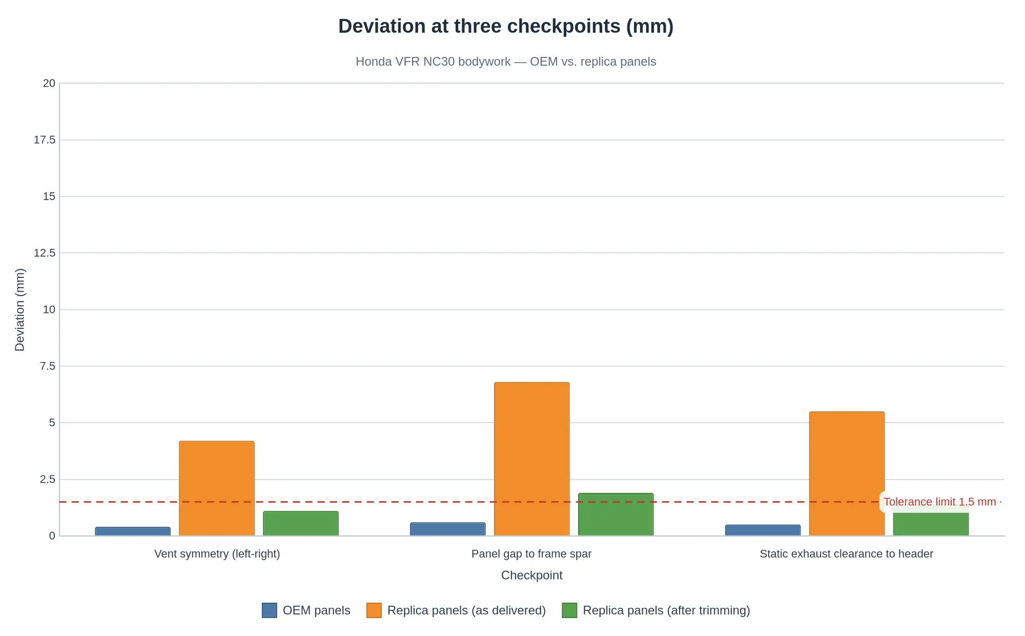
Log every value three times: OEM panel, replica as delivered, replica after trim. Take each checkpoint in two fastener states, everything finger-tight then fully torqued in sequence. If a number moves more than 1 mm between the two, you have a clamping problem rather than a panel problem, and trimming would be a mistake.
This is where the comparison table earns its keep. A replica reading 5 mm off at the mid-pipe seam, while the OEM panel reads 0.5 mm at the same station, is telling you the mould differs, not that the bike moved. If you are still sourcing panels, compare a range of custom Honda fairings before committing to a mould, because vent geometry and header relief vary between suppliers.
Recommended tolerance ranges
Working limits for a road or track-day build, not factory homologation figures. Re-measure at ride height with the suspension loaded if you run very stiff springs or a lowered ride height.
| Measurement | Reference / datum | Recommended tolerance | Action if exceeded |
|---|---|---|---|
| Vent symmetry, left vs right height | Tape at vent leading edge, from spar datum | +/- 1.5 mm | Check mount order, then panel |
| Vent symmetry, left vs right width | Tape across vent opening at mid-height | +/- 1.5 mm | Check mount order, then panel |
| Vent alignment to spar line | Tape from spar datum to vent trailing edge | +/- 2.0 mm | Adjust bracket, do not trim |
| Minimum static exhaust clearance, header | Feeler gauge, closest point | 12 mm minimum, 15 mm target | Re-route, heat shield, or re-trim |
| Minimum static clearance, mid-pipe seam | Feeler gauge at weld seam | 12 mm minimum | Inspect for contact witness marks |
| Panel-to-spar gap | Caliper or tape, three stations per side | 3-5 mm, +/- 1.0 mm variation | Shim or slot mount |
| Panel-to-panel step | Straight edge plus feeler gauge | +/- 1.5 mm | Adjust fixing sequence |
| Header pipe OD at station | Calipers, perpendicular | Record only – no nominal | Use value for clearance math |
On a track bike, resist chasing the tight end of every range. Twelve millimetres of static exhaust clearance at the header sounds generous until the pipe grows and the engine moves on its mounts. Ten is the floor, not a target.
Tolerance stack-up or a single bad panel?
This question saves panels. A stack-up is several small, individually acceptable errors adding up across the frame, the brackets, engine position and the mould. A single-panel defect is one mould or one trim that is out on its own. Four tests, run in order:
- The swap test. Fit the OEM panel and the replica to the same side with the same fasteners. If the replica is out and the OEM is not, the fault travels with the panel.
- The location test. Fit the replica to the opposite side. If the deviation follows the location rather than the panel, something on the bike is out: bent bracket, tweaked subframe, offset engine.
- The isolation mount. Remove every other panel and fit only the suspect one. Errors that vanish when the bodywork comes off are clamping errors.
- The datum re-check. Loosen everything, re-torque in sequence, measure from the spar again. Numbers that move more than 1 mm were measuring assembly order, not geometry.
Consistency is the tell. An error at one checkpoint, on one side, is a panel defect. The same error at several checkpoints on both sides, growing as the bolts tighten, is stack-up, and no amount of trimming will fix it.
Write the numbers down, leave the datum tape dots on until the build is finished, and carry the log into the trimming stage. Ten minutes with a feeler gauge beats a week waiting for a replacement panel.
Exhaust-to-Fairing Clearance: What the Numbers Actually Say
The exhaust is the least forgiving part of the NC30 bodywork equation. The rear-bank header pipes sweep up and out within millimetres of the lower cowl, and the collector sits directly behind the belly section. Every figure below was taken cold, suspension at static sag, panels seated against their OEM mounting points: no spacers, no shimming, no “adjustment” to make a bad panel fit.
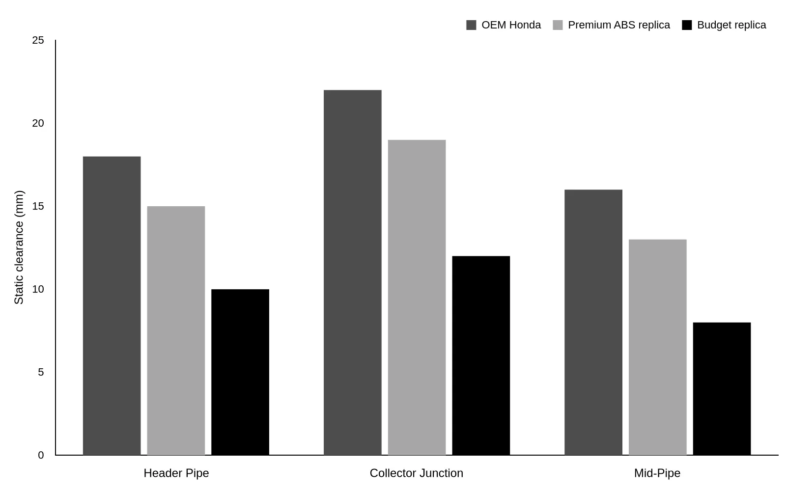
Measured Static Clearance (mm)
| Reference Point | OEM Honda | Premium ABS Replica | Budget Replica |
|---|---|---|---|
| Header Pipe | 18 | 15 | 10 |
| Collector Junction | 22 | 19 | 12 |
| Mid-Pipe | 16 | 13 | 8 |
Reading the Chart
The pattern is consistent and it is not subtle. Premium ABS replicas give up about 3 mm at each checkpoint, a margin reflective tape and careful alignment will absorb. Budget panels give up 6 to 10 mm, and the 8 mm at the mid-pipe is the number to worry about: that is where the pipe runs hottest and the fairing wall is thinnest. Once the system is at temperature on a track day, 8 mm of cold clearance becomes contact, then blistering, then a hole burned through the belly pan.
The collector junction is the least critical of the three. Honda’s 22 mm leaves genuine headroom even after a replica compromise, and no set in this sample closes that gap below 12 mm without intervention.
Why the Gap Exists
Budget tooling is pulled from a single mould and laid up fast, so the wall thickness wanders. It is often thin at the tabs and the vent lip, and sometimes 2-3 mm heavy through the lower cowl, exactly where it crowds the pipe. Combine that with vent openings cut smaller than the original pattern, which restricts airflow through the zone that needs it most, and you have a panel that crowds the exhaust while removing the cooling that would have protected it. Bodywork from tighter tooling holds both dimensions at once.
If you want the widest vent openings with genuine clearance tolerance, start from a set built to the original Honda pattern rather than a generic replica: browse custom Honda fairings built to OEM dimensions and check the specified wall thickness before you buy.
Practical takeaway: below 12 mm of static clearance at the mid-pipe, treat the panel as a fitment defect, not a tuning opportunity.
Trimming and Adjustment: Side Vents and Exhaust Clearance
Aftermarket NC30 bodywork rarely drops straight out of the crate. The vent area is the tightest packaging point on the bike, with the rear-bank header and the fan shroud sitting within millimetres of the duct, so the trimming phase is where a full bodywork build is made or ruined. Work in passes and treat every cut as irreversible, because it is.
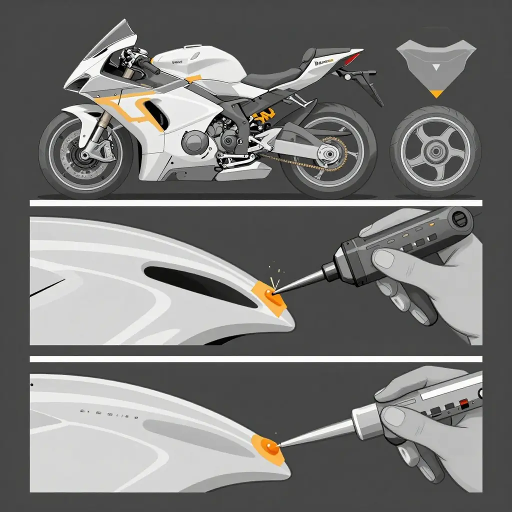
Step 1: Mark the relief cut before the tool comes out
Fit the panel dry with the exhaust and radiator in place, then transfer the interference point onto the inside of the panel with a paint pen. Take the panel off and run two parallel strips of low-tack masking tape as the cut boundary. The tape gives the tool a hard, visible edge and keeps a skating bit off the paint. Draw the line on the tape with a fine-tip marker rather than on the panel, and index it against a straightedge or a flexible curve so the left and right side vent openings mirror each other. Matching an OEM panel? Lay the original over the replica and scribe through the vent corner radius; that radius is the most visible detail on the bike once it is painted.
Step 2: Cut with a rotary tool at low speed
Use a fresh 3.2 mm high-speed cutter or a small tungsten carbide burr and hold the tool in the 10,000-15,000 rpm range. High rpm melts ABS rather than cutting it: the kerf closes behind the bit, the edge smears and the line goes with it. Grip the tool like a pencil, run the bit in one direction along the tape edge, and let the flutes do the work. Push hard and you generate heat, and heat is what warps a 1.5 mm vent lip. Cut 2-3 mm inside the final line and finish to the marked edge with abrasives. Light dust extraction, or a damp cloth on the bench, keeps ABS swarf out of the paint.
Step 3: Controlled sanding and edge sealing
Step the abrasives: 120 grit to true the line, 240 to clear tool chatter, 400 to break the sharp arris. Chamfer the inside edge by roughly 0.5 mm, because a square edge on ABS is where a vibration crack starts. Seal the freshly cut material by wiping the edge with an ABS-compatible solvent (acetone or MEK on a cotton bud) to reflow the surface, or kiss it with a hot-air gun on low. Never use an open flame on bodywork. The material goes from glossy to sagging in about two seconds.
Step 4: Reinforce the trimmed vent edge
A trimmed opening loses the moulded-in stiffness of the original duct, so put some back. Plastic welding with an ABS rod of matching composition is the strongest repair and the one that survives paint: V-groove the joint, weld in overlapping passes, dress it flush. Where a welder will not reach, a structural two-part adhesive such as 3M DP8010 or Devcon Plastic Welder does the job; scuff to 80 grit, clean with isopropanol, and back the joint with mesh or a gusset instead of trusting a butt joint. Any raw edge sitting in the exhaust’s radiant path gets reflective foil tape on the inside face.
Step 5: Re-check clearance after every cut
Refit after every pass, without exception, and check exhaust clearance with the panel fully torqued and the suspension cycled through its stroke. Static cold clearance is only half the story. A header that clears by 12 mm cold can touch the vent duct after twenty minutes of running.
| Clearance point | Cold static target | Hot-idle re-check |
|---|---|---|
| Vent duct inner face to radiator fan shroud | 8 mm | Confirm no witness marks |
| Lower side panel to rear-bank header | 12-15 mm | Confirm no contact at full compression |
| Vent opening lip to frame spar | 6 mm | Confirm no rubbing at steering lock |
| Belly pan to collector | 15 mm | Confirm no blistering after heat cycle |
Run the steering lock to lock and bounce the front end while you watch the vent edge. A panel that clears at rest can still foul when the fork compresses and the fairing stay flexes.
When to adjust the fairing stay instead of trimming
If the vent openings are asymmetric, if the panel sits proud at the frame mounting points, or if both sides foul the exhaust in the same direction, the problem is the stay. Trimming to correct a bent or out-of-tolerance stay moves the error into the panel and leaves you with a permanently lopsided bike. Slot the stay’s mounting holes 2 mm, add stainless washers as spacers to push the bracket outward, or replace a distorted bracket outright, and check the stay for twist with a straightedge across the mirror mounts before you touch a panel. Confirm frame, stay and subframe geometry first; trim second.
Why repeated small cuts beat one large cut
ABS comes off in seconds and goes back on in hours. A 2-3 mm pass gives you a fresh fitment check, keeps the tool cool, and lets you stop the moment the interference disappears, which is usually sooner than you expect. One aggressive cut typically overshoots the opening by 5-10 mm, destroys the moulded radius and drags you into filler and reinforcement work that was never needed. Sanding and welding creep as well: the edge moves while you finish it, so the last 1 mm is always best taken off by hand.
- Cutting to the interference point rather than past it. The panel needs clearance, not a gap; an oversized vent looks amateur under paint.
- Using a sanding drum at full speed to “shape” the vent line. It rounds the corners, loads up with melted ABS and loses the crisp radius the NC30 silhouette depends on.
- Skipping the hot re-check. A cold fit proves nothing about exhaust clearance until the header has been through at least one heat cycle.
If you are building a complete NC30 or RC30-look project, panels from one consistent mould set save hours of trimming, so browse custom Honda fairings for the NC30-compatible options before you commit to a mixed set.
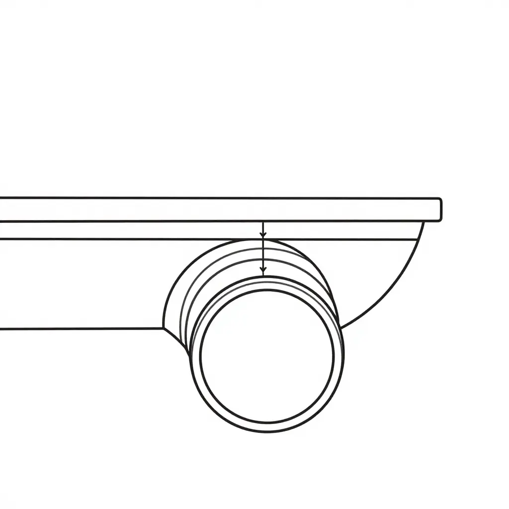
Cross-section of the exhaust-to-fairing interface: the pipe circle, the inner face of the lower fairing panel, the clearance gap between the two reference lines, and the heat-shield layer shown as a separate offset arc. Use the panel wall and the outer pipe surface as your datum points when trimming.
Thermal Management and Heat Shielding
The side vent openings are the working end of the fairing’s cooling strategy. The rear-bank header pipes sit deep inside the bodywork envelope, and the louvred slots ahead of the knee recess let air that has already crossed the radiator and the rear bank escape rearward into the low-pressure zone behind the frame spar. That through-flow does two jobs: it convects heat off the panel skin, and it keeps the exhaust pocket from turning into a stagnant oven. Compromise it, with a trimmed opening, filler, a decal stack or an oversized pipe pushed against the panel, and a ventilated compartment becomes a hot box.
Why Vent Openings Must Stay Unobstructed
Every millimetre of open area lost at a vent cuts the mass flow across that panel. Surface heat transfer is convective: it scales with air velocity and with the temperature difference between panel and air. Halve the effective aperture and you roughly halve the velocity, and skin temperature climbs until radiative and conductive losses balance what the header is radiating. The relationship is not linear either. As a vent closes down, the pocket stratifies, the hottest air sits directly against the panel, and the curve steepens sharply past about 50% blockage.
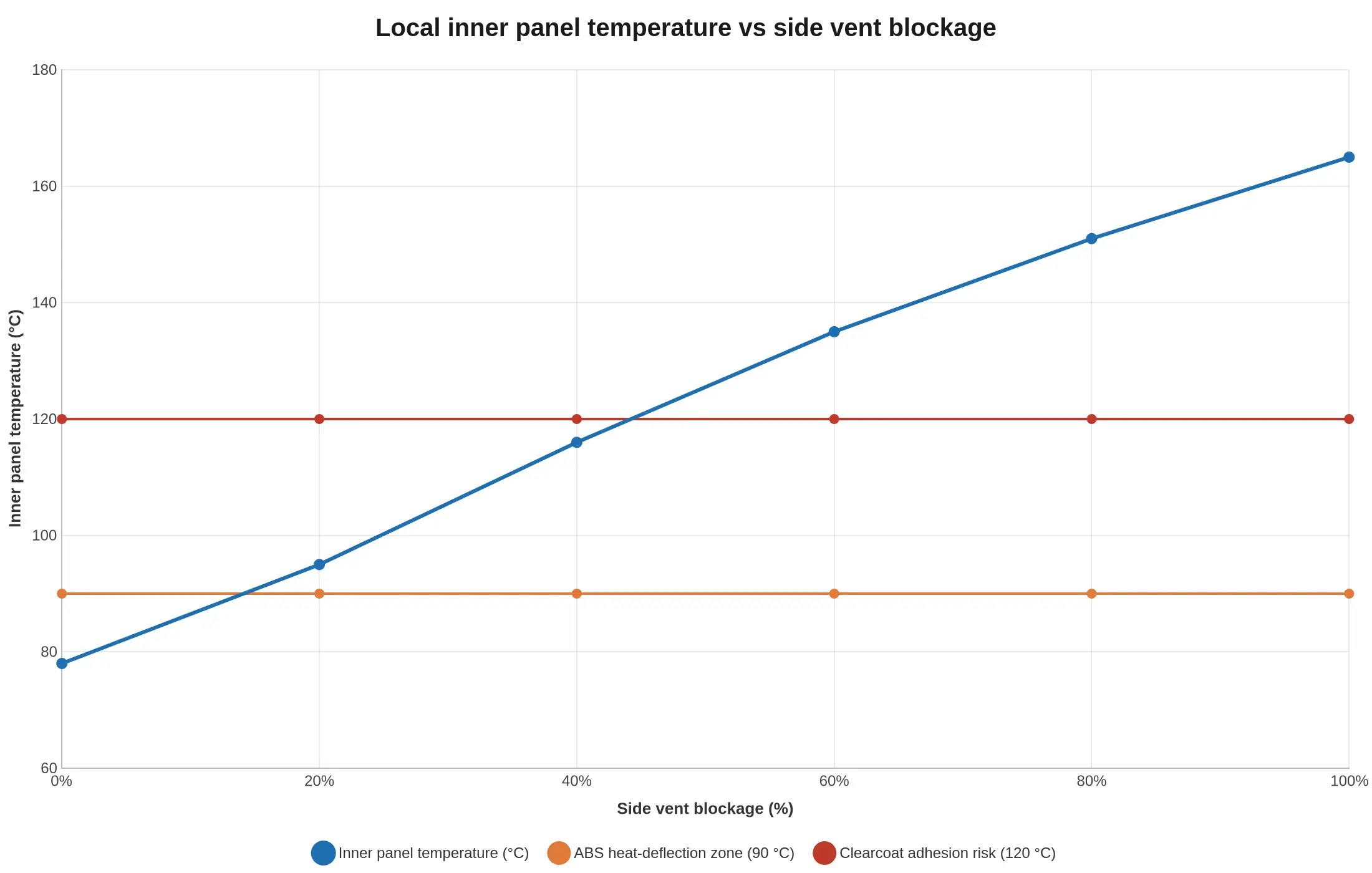
The usual culprits are easy to spot:
- Exhaust clearance taken out by pushing a replica panel inward rather than reshaping the header or fitting a proper spacer.
- Reflective material applied over the vent slots instead of around them, which blocks the airflow and traps radiant load.
- Filler or fibreglass laid across the back of the louvres while repairing a cracked relief area.
- Oversized aftermarket mid-pipes that physically block the rear outlet of the vent path.
- Paint and lacquer build-up on the louvre edges, which closes the slot further than most builders expect.
ABS Behaviour Thresholds
NC30 panels are ABS, a thermoplastic rather than a thermoset. It does not char before it fails; it softens, creeps and distorts, usually warping the relief areas around the vent and pulling the louvre faces out of line with the adjacent panel.
| Inner panel temperature | ABS condition | Paint system condition |
|---|---|---|
| Up to 80 °C | Fully stable, no creep | No change |
| 80 – 95 °C | Approaching heat-deflection zone; slow creep possible under fastener preload | Borderline; softens the primer interface over long exposure |
| 95 – 120 °C | Visible softening, vent edge distortion, panel bowing | Clearcoat flow and micro-blistering possible |
| Above 120 °C | Permanent deformation, gloss loss, surface grazing | Adhesion loss, edge lifting, cracking at relief cuts |
| Above 150 °C | Localised sag and thinning under clamp load | Film failure requiring full refinish |
Measure it rather than guess. Ride or run the bike to full operating temperature on a warm day, then shoot an infrared thermometer at the inner face within 20 mm of the vent, at the relief cut-out behind the knee, and at the closest point of the header. A healthy build reads 70-85 °C at the vent and stays under 100 °C at the tightest header clearance. Anything at 105 °C or above on the inner surface is a shielding or airflow problem, not a paint problem.
Shielding Placement and Exhaust Clearance
Reflective tape and aluminium heat shielding do different jobs. Aluminised glass-cloth tape reflects radiant load back toward the pipe and is typically rated for 200-250 °C continuous with short excursions higher. A thin aluminium shield on a standoff re-radiates the load and breaks direct conduction into the panel. Where clearance is genuinely tight, use both.
- Clearance targets: 15 mm between header outer wall and inner panel surface where you can get it; 10 mm is the absolute floor and should be shielded. Below 10 mm, stop and change the pipe routing or trim the vent surround properly.
- Coverage area: shield the inner surface for at least 100-120 mm either side of the closest pipe, extending past the vent opening on both edges.
- Vent discipline: cut shielding around the vent apertures, never across them. A shielded panel with a blocked vent still overheats, just more slowly.
- Standoff: a 3-5 mm air gap behind an aluminium shield outperforms tape bonded flush, at the cost of 4-6 mm of clearance.
- Application: degrease with isopropyl alcohol, apply above 15 °C, roll air pockets out from the centre, and seal the edges with high-temperature foil tape so fuel mist and road grime cannot lift the adhesive.
- Relief areas: the moulded reliefs and fastener bosses behind the knee are thin and highly loaded. Shield them, and check the vent surround for stress whitening at every service interval.
Fit, air-test, then paint. A heat cycle before refinishing tells you whether the vent path is genuinely open and whether the custom Honda fairings you have chosen need extra shielding at the header pocket before expensive coating work goes on top. Vents, clearance and bodywork are one system: get the airflow right and the shielding only has to handle the residual radiant load, which is the margin ABS and a good clearcoat are built for.
Where the Heat Actually Goes
Which panels are working hardest is worth knowing before you commit to reflective mat or a vent cut-out. On a full Honda fairings build for the VFR400R, heat load does not spread evenly across the skin: it concentrates behind the exhaust path and along the narrow edges where hot air accelerates through the side vent openings. The distribution below reflects typical road and track use with the OEM header and mid-pipe in place.
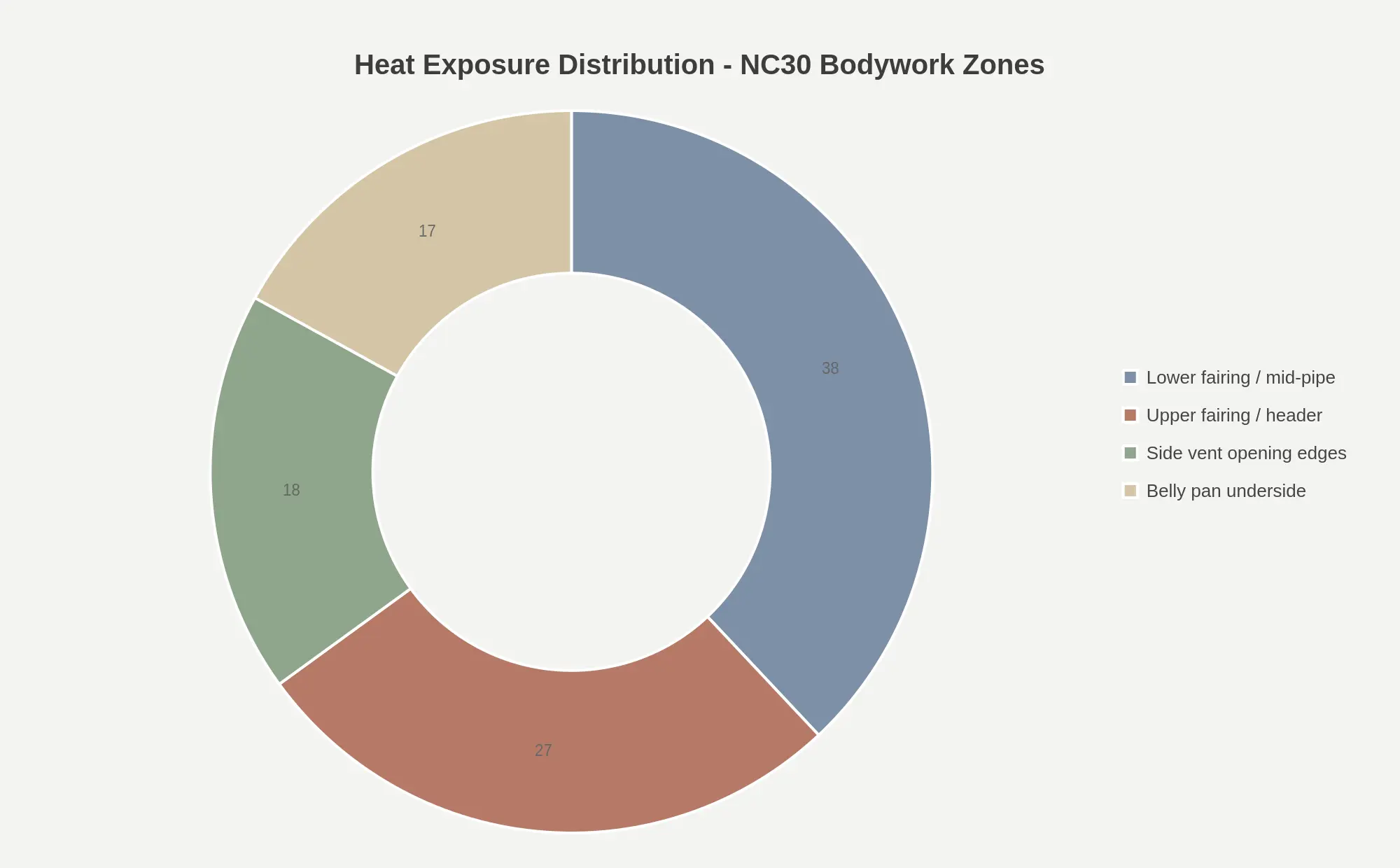
Reading the ring: the lower fairing near the mid-pipe carries the largest share, so shielding pays off there first. The upper fairing near the header comes next, and it is also the zone most sensitive to replica panel thickness and resin quality. The two smaller slices, vent edges and belly pan underside, matter less for radiant soak and more for airflow: pinch either one and the heat it represents gets pushed into the panels sitting beside it.
Prioritise shielding on the lower and upper fairing, then protect the vent edges by keeping the opening clear rather than covering it. On aftermarket bodywork, check clearance at the vent throat before trimming, because a 3-5 mm shift at the opening edge changes the flow path more than most builders expect.
Frequently Asked Questions: NC30 Vents, Clearance and Fitment
Do replica VFR NC30 side vent openings match OEM flow area?
Quality replicas pulled from OEM masters typically land within 3-5% of the original side vent flow area. Budget panels often shrink the aperture by 8-12%, because a heavy gelcoat and fibreglass layup thickens the vent lip. Measure opening height and width with calipers against the stock louvered insert before paint: a restricted vent raises under-cowl air temperature and pressure. Panels in a custom Honda fairings range are laid up with a trimmed vent lip that keeps the OEM opening within tolerance.
What is the minimum safe exhaust clearance on an NC30?
Not less than 10 mm (0.4 in) of static, cold clearance between the exhaust pipe or heat shield and the inner skin of the lower fairing, opening up to 15-18 mm around the rear header, where radiant load peaks on the 4-into-2-into-1 system. Below 8 mm, contact is likely once the pipe expands and the panel flexes at speed, so shim the mounting points rather than assuming the gap holds. Verify it with the suspension loaded and both wheels on the ground, not only on a paddock stand.
Does trimming the vents void replica panel warranty expectations?
Cleaning up or opening a moulded side vent is normal fitment work on NC30 bodywork and does not by itself void coverage, provided the cut stays inside the moulded vent boundary and is finished cleanly. What does sink a claim is cracking that starts from a ragged cut, unsealed fibreglass edges, or holes drilled outside a reinforced mounting boss. Seal the trimmed edge with resin and photograph it before assembly if you may ever claim a moulding defect.
Is heat shielding still necessary with correct clearance?
Yes. Even at a healthy 12 mm gap, run aluminium-backed glass fibre or a moulded ceramic blanket on the inner skin above the rear header and under the collector, because sustained track pace will soften resin and print a visible sag line through radiant heat alone. Shield the fairing, not the pipe: wrapping a header on a road bike traps moisture and accelerates corrosion. The shielding buys margin for heat soak in traffic and slow pit lanes.
How do I confirm vent symmetry after installation?
Measure from the fairing centreline seam to the inner edge of each vent with a tape or laser, then compare the aperture diagonals. A 2 mm mismatch is acceptable; 5 mm or more points to a twisted panel or a bent stay. Hang the upper and lower sections with the mirrors and stay fitted, then sight both vents against a plumb line dropped from the mirror stalks. Do not trim fibreglass to chase asymmetry until the stay and every mounting point are confirmed true.
Does a full bodywork build need a modified fairing stay?
Almost always, yes. Tired OEM stays bend at the mirror mounts, and a 1-2 mm error at the stay becomes a 6-8 mm misalignment at the side vents and lower cowl once the panels are stacked, so a reinforced or CNC stay with slotted mirror tabs is the practical fix. Fit the stay first, hang the bodywork dry, and only then trim vents or drill mounting holes. Chasing alignment in the fibreglass instead of the bracket is how owners end up with a permanently uneven NC30 front end.
Sourcing and Supplier Guidance: Choosing an NC30 Fairing Supplier
Buying bodywork for a VFR400R is not like ordering a part number for a modern Fireblade. The NC30 left production in 1992, its panels were hand-fitted at the factory, and the aftermarket has filled the gap with everything from good replica moulds to rough fibreglass shells that need hours of fettling before they sit straight. Whether a build comes together in a weekend or fights you for a month is usually decided before you pay, at the enquiry stage. A supplier who knows the product answers in millimetres and material grades, not adjectives. If the reply to “will it fit?” is “yes, perfect fit”, keep looking.
Specification questions to ask before you commit
Put these four areas in writing. Any supplier worth dealing with either has the figures to hand or offers to measure a set from stock.
- Panel material and wall thickness. Injection-moulded ABS, an ABS/PC blend, or compression-moulded fibreglass? Ask for nominal wall thickness: road-oriented ABS usually lands in the 2.5-3.0 mm band, and anything noticeably thinner will flex at the mounting tabs and drum under paint. For fibreglass, ask about gelcoat, resin type and whether the panels arrive primed or bare.
- Vent opening dimensions. The NC30 side vents are the exit path for hot air out of the engine bay, and a mould that closes the aperture by 10 mm costs cooling quietly. Ask for the internal aperture height and width at the narrowest point, and whether the duct flange and mesh frame are moulded in or left for you to fabricate.
- Exhaust relief cut. Confirm whether the lower panel carries the relief for the collector and mid-pipe, whether that relief is in the tool or hand-trimmed afterwards, and what clearance exists at the tightest point. Ask specifically about left- and right-hand differences, and whether the shape still works with a 4-into-1 aftermarket system instead of the original 4-into-2-into-1 and its single silencer.
- Mounting hole accuracy. Pre-drilled, dimpled for drilling, or blank? Ask for hole diameter (6 mm is the common convention), whether positions are jig-drilled from an OEM frame or copied panel to panel, and whether the tabs use brass inserts. Ask for the stated positional tolerance in millimetres rather than being told the holes are “OEM spec”.
| Specification point | Question to ask | A credible answer sounds like |
|---|---|---|
| Panel material | ABS, ABS/PC or fibreglass? | Named material grade plus nominal wall thickness |
| Vent aperture | Internal height and width at narrowest point? | Actual measurements in millimetres |
| Exhaust relief | Moulded or trimmed? Clearance at tightest point? | Described shape plus a measured clearance |
| Mounting holes | Pre-drilled or dimpled? Tolerance? | Hole diameter, jig source, stated tolerance |
| Finish | Primed, gelcoat or bare? | Specific surface preparation described |
How to request fitment confirmation
Fitment confirmation should be a documented process, not a conversation. Send your enquiry with the model year, the market variant (JDM, UK and European NC30s differ in detail) and the exact panel list you intend to buy: upper, sides, lower, tail, mudguard, air ducts. Ask for confirmation panel by panel. The strongest reply includes photographs of the same set test-fitted to a bike, ideally showing the tank-to-upper gap, the side-panel-to-frame join and the lower-to-collector clearance.
Ask three practical questions in the same message: what happens if a panel does not align, what the return or replacement window is, and what the lead time is in business days. A supplier with a broad catalogue, such as the Honda fairing range at Summit Fairings, can normally cross-reference your list against the correct mould and confirm it in writing. Keep the reply. It is your reference point if a panel arrives with a shifted tab.
Ready-to-ship versus custom production runs
Price and availability behave differently on each route, and the choice usually comes down to deadline rather than budget.
| Factor | Ready-to-ship stock | Custom production run |
|---|---|---|
| Price | Fixed, listed per set | Higher per set, quoted per order |
| Lead time | Days, subject to stock | Weeks, scheduled in batches |
| Colour choice | Limited to what is moulded and painted | Open – including race layouts and replica schemes |
| Flexibility | Take the set as offered | Panel list, finish and graphics can be specified |
| Best for | Track-day repairs and riders mid-build | Restorations and RC30-style replica projects |
Ready-to-ship sets are priced and dispatched immediately, which makes them the pragmatic choice when a lowside has taken out a side panel two weeks before a track day. Availability is finite: once a batch is gone, that colourway may not return. Custom runs work the other way. You gain control over panel material, vent detail and paint scheme, and you wait for a production slot. Browse the ready-to-ship fairings when timing matters most, and compare against custom Honda fairings when the brief is specification-led.
Summit Fairings stocks over 3,000 styles covering almost all motorcycle models and prices them 10-40% below other sites, with a six-hour response guarantee on enquiries, which matters when you are waiting on aperture measurements before committing to a mould. If you are still narrowing down a scheme, the featured products section shows what a complete NC30 set actually comprises. Ask the questions, get the answers in writing, and the panels that arrive will be the ones you expected.
Conclusion and Build Summary
On a Honda VFR400R NC30, two measurements decide whether the panels fit: the side vent openings and the exhaust clearance. Panel gaps, decal placement and fastener alignment all follow from those two. The vents control how the mid-panels index against the frame and how much air reaches the rear cylinder head. The clearance decides whether the lower fairing survives its first hard ride or melts into the header pipe.
The workflow is short. Measure vent geometry against the OEM template and the radiator shroud before any cutting. Measure exhaust clearance at the tightest point of the lower section with the suspension compressed. Trim in small passes and refit between each one. Shield wherever the panel sits inside a conservative clearance band. Re-check every number after the first few heat cycles, once the plastics have settled.
That order is fixed: verify vent geometry, measure exhaust clearance, trim incrementally, shield against heat, then re-check after heat cycles. Owners sourcing Honda VFR NC30 fairings should treat it as non-negotiable, because reversing the trimming and clearance steps produces panels that look correct on the bench and fail on the road.